CFD Analysis of Hydrofoil Flow and Cavitation-Juniper Publishers
Juniper Publishers-Open Access Journal of Engineering Technology
Abstract
The present paper deals with a complete computational solution for non-cavitating and cavitating flow around symmetrical hydrofoil disposed of a winglet. First, the hydrodynamic characteristics of the hydrofoil were analyzed for different advance velocity values. Numerical investigations were carried out by imposing boundary conditions favoring the cavitation inception. In this application, the mean flow is described by the Reynolds equations which must be added to the Singhal cavitation model implemented in the code Fluent. The results confirm a cavitation inception on main parts of the hydrofoil namely: the wing and the wing-winglet junction.
Keywords: Numerical simulation; Hydrofoil; Cavitation; Hydrodynamic coefficients; FluentIntroduction
The main role of hydrofoil is to raise the hull of a boat out of the water and keep well dynamically to reduce the wave’s effect and diminish the power required to reach high speeds. This causes the presence of an interface (water / vapor) favoring the occurrence of cavitation. Cavitation is frequent and often much unknown phenomenon, cavitation occurs in liquid subjected to sudden variations in pressure. Cavitation is manifested by the appearance of small bubbles or enormous cavities, which form and then implode within milliseconds. It causes severe nuisances such as material erosion, noise and falling performance in hydraulic or marine installations. Zi-ru Li et al. [1]. studied the prediction of the cavitation risk by a multi-phase code using the RANS approach. A comparison of cavitating and non-cavitating flow around a NACA66 hydrofoil is studied numerically by Bertrand J et al. [2] The Large-Scale Simulation (LES) was added to a homogeneous cavitation model to calculate the pressure, velocity, vapor volume fraction around the hydrofoil. This research provides a better understanding of the mechanism leading to cavitation-excited pressure pulses, which will facilitate the development of technical designs to control these vibrations [3].
In the present work, a study of the performances of a winglet hydrofoil in a cavitating and non-cavitating flow is presented. Numerical investigations were carried out by using the Gambit and T Grid codes, for the mesh, and Fluent code for the flow calculations.
Mathematical Formulation
The Mixture model implemented in Fluent code assumes that the working fluid is a single fluid with a homogeneous mixture two phases (liquid and vapor). Therefore, RANS equations are solved for the mixing fluid. The constitution of the density of each phase is described by means of a scalar volume fraction. The relationship between the different volume fractions is linked by:

Resolution Procedure
The first aim of this work consists in processing by numerical simulation the non-cavitating incompressible three-dimensional flow around a hydrofoil equipped with a winglet. This, using the RANS approach and by testing several advance velocities for the correct prediction of the hydrofoil hydrodynamic characteristics. The second aim is a comparison of a two-dimensional and three-dimensional cavitating flow around the same configuration.
Geometry
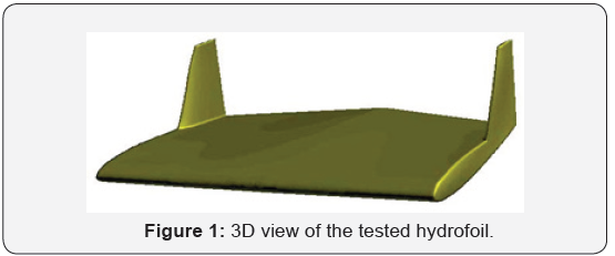
The tested hydrofoil is created from two parts (wing part + winglet part) as shown in (Figure 1). The base of the hydrofoil is made up of two profiles with an average rope of C = 320 mm, while the winglet part is drawn from a NACA0009 profile with an average cord of C = 170mm.
Calculation Domain
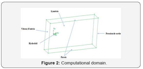
The computational domain was created for only 1/2 of the geometry considering the symmetry condition. The calculation domain is rectangular with a length of 5000mm, a width of 1000mm and a height of 1500 mm. The geometry is implanted in the calculation domain at 300 mm from the inlet. (Figure 2) illustrates the boundary conditions that were considered in this simulation where a 1/ 2 model of the hydrofoil was tested.
Mesh Generation
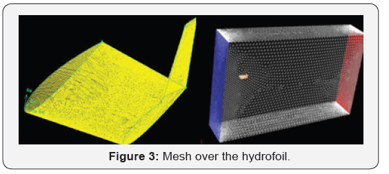
A triangular hybrid surface mesh was generated using the Gambit processor. Indeed, triangular meshing elements have been placed on the hydrofoil faces (Figure 3) using the sliding mesh technique which consists of using very small elements on the hydrofoil edges and enough large elements as it moves away from the edges [4]. To solve the boundary layer problem, the T Grid code was used to generate the volume meshing in two steps. First, prismatic elements stacked in fifteen layers on the hydrofoil were created. The height of the first cell was set at 0.00001C to capture the flow within the viscous sub-layer. Then, the mesh between the prismatic elements and the boundaries of the domain was formed. The number of cells thus generated is 694336 which is equivalent to 194700 nodes.
Results and Discussion
The check of the hydrodynamic performances of the designed hydrofoil is imperative. This is possible by simulating the noncavitating flow using the Fluent code. the Kω -SST turbulence model has been chosen [5]. A comparative study was carried out for different advance velocities: 3m/s, 6m/s, 8m/s and 10m/s. Figure 4 shows the distribution of the y+ on the hydrofoil. Examination of this distribution shows that the value of y+ is less than 1, that the mesh penetrates the viscous sub-layer of the turbulent boundary layer and the Kω -SST model is well adapted to this type of mesh as it is a low-Reynolds model.
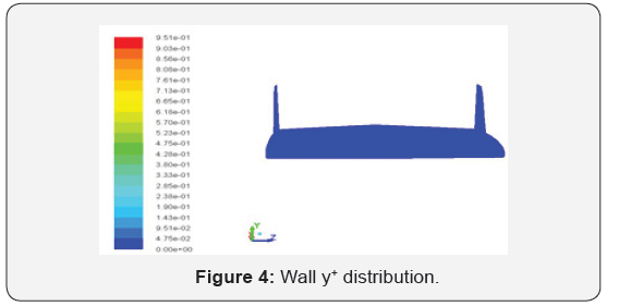
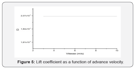
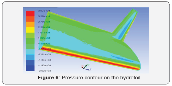
Figure 5 represent the lift coefficient CL variations as a function of the inlet velocity. Examination of this curve shows that the CL is constant with the velocity variation. The same geometry was tested for the unsteady cavitation case for the same boundary conditions and adopting the same turbulence model. It should be noted that the pressure at the outlet is used for calculating the cavitation number as a reference instead of the inlet pressure. This is since this pressure remains fixed during the calculations. It should be noted that these calculations were carried out for an input velocity equal to 8m/s. In this application, the mean flow is described by the Reynolds equations to which must be added the Singhal cavitation model implemented in the Fluent code. Figure 6 shows the pressure contours on the hydrofoil where it is clearly seen that cavitation can be occur on the winglet area.
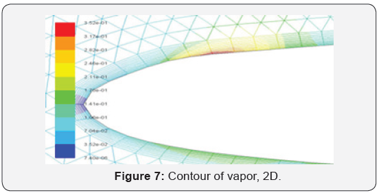
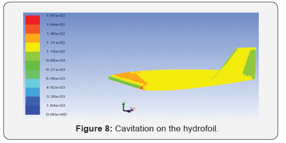
Calculations of the cavitating flow around the profile located at z=0.16C made it possible to obtain the distribution of the vapor phase around the profile, (Figure 7) [6]. It can be observed a vapor area near the leading-edge witch confirm the cavitation inception in this zone. Figure 8 shows the hydrofoil zone where the cavitation is expected to occur, namely the wing and the winglet part. However, the vapor area obtained by the 3D calculation is different from that obtained by the 2D calculation. It seems that this last calculation indicates an early cavitation. Results show that the maximum vapor area is situated at the free end of the wing part which is the seat of the type vortex. In this work a numerical simulation applied to the cavitating and noncavitating flow around a winglet hydrofoil using the commercial Fluent code is presented. Investigations were carried out in threedimensional for the hydrofoil and two-dimensional for the profile near the winglet-winglet junction where cavitation is suspected [7,8]. Results show a cavitation inception on the wing extremity and winglet leading edge.
Conclusion
In this work a numerical simulation applied to the cavitating and non-cavitating flow around a winglet hydrofoil using the commercial Fluent code is presented. Investigations were carried out in three-dimensional for the hydrofoil and two-dimensional for the profile near the winglet-winglet junction where cavitation is suspected. Results show a cavitation inception on the wing extremity and winglet leading edge.
For more articles in Open Access Journal of Engineering Technology please click on: https://juniperpublishers.com/etoaj/index.php


Comments
Post a Comment