Stator Fault Detection for the Input Output Control of the Permanent Magnet Synchronous Motor - Juniper publishers
Juniper Publishers - Open Access Journal of Engineering Technology
Abstract
In this paper, a simple dynamic model for a PMSM with
inter-turn winding fault in closed loop. The control of the PMSM is
assured by the input-output control. The objective of this paper is the
detection and location of the stator winding fault severity of PMSM. To
achieve this objective, a mathematical model that can describe both
healthy and fault conditions is developed. Simulation results match the
observations of this type of fault in the literature.
Keywords: Permanent magnets synchronous machine; Inter turn; Fault detection; Input-output control Introduction
Permanent magnet synchronous motor PMSM has received
widespread acceptance, mainly in high performance of its applications
for renewable energy generator or industrial servo applications of
accurate speed and position control. This is due to some of its
excellent features such as super power density, high torque to current
ratio, fast response and low noise [1].
Nonlinear control has the advantage of separately
current and torque. With this control technology, engine model is broken
down into two independent systems mono variable linear. Each subsystem
is an independent control loop of a given variable (speed, torque,
current etc.). The dynamics of the linearized system is chosen through
optimal taxation of poles [2].
The PMSM are generally robust, their frequent
exposure to severe circumstances inclines them to certain fault
conditions after continuous operation. The possible fault modes in PMSM
include electrical and mechanical sources [3].
Statistics show that the most electric motor failures are due to
electrical faults, among which the stator winding faults constitute the
largest portion [4].
Stator winding faults usually are caused by insulation breakdown
between coils in the same phase or different phases. While the winding
"short" usually emerges locally as an incipient fault, it can propagate
rapidly, culminating in the failure of the entire phase. This is due to
the increased ohmic heating associated with the high current in the
shorted portion of the winding, which eventually leads to a significant
rapid temperature increase and causes faster deterioration of the
insulation system [5]. Therefore, an effective diagnostic system for these faults in motors is necessary to improve the reliability of such motors.
The mathematical analysis and computer simulation
are more versatile and cost effective methods for gaining insight into
the system dynamics under fault operating conditions. Recently, several
studies on faulty electric machine dynamic modeling have been published.
These studies use various methods for different purposes [6].
Fault modeling is becoming an important part of the fault diagnosis
design process. In this paper, a new model for the stator winding fault
of PMSM is proposed based upon the coupled magnetic circuit principle.
The model is compatible with both healthy operation and operation under
asymmetrical stator winding fault (turn-to-turn short) conditions.
Simulation results of the fault model match the observations of this
kind of fault in the literature. In the developed fault model, two
parameters are used, one to represent fault location and one for fault
severity. If these two parameters can be identified and are beyond a
certain range, then the occurrence of a stator winding fault can be
concluded.
In general, monitoring and diagnosis require the
detection and analysis of signals containing specific information
(symptoms or signatures) that characterizes the degradation of the
machine [7].
FFT analysis of one of the stator currents has become a standard
procedure for diagnosing the state of a permanent magnet synchronous
motor. However [8],
Even though the method gives successful results for stationary signals,
it is not successful for non-stationary signals due to the inadequacy
of the FFT method. Since PMSMs are operated according to the determined
acceleration and deceleration reference speeds, both the amplitude and
the frequency of the current drawn in these regions are dynamic [9].
Dynamic Model of the PMSM with Inter Turn Fault
An inter-turn fault denotes an insulation failure
between two windings in the same phase of the stator. The insulation
failure is modelled by a resistance, where its value depends on the
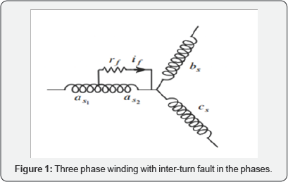
fault severity. The stator winding of a PMSM machine with inter-turn
fault is represented in Figure 1, where the fault is occurred in the phase as and (rf ) represents the fault insulation resistance. The sub-windings (as1 ) and ( a s2 ) represent the healthy and faulty part of the phase winding a respectively.
When the fault resistance (rf)
decreases toward zero, the insulation fault evaluates toward an
inter-turn full short-circuit. The evolution of fault insulation
resistance between rf =∞ and rf=0 is
very fast in most insulation materials. It is important to predict the
inter-turn fault when it is not high developed and the fault resistance
is still not very near to zero. Therefore, in our fault model, the fault
insulation resistance is included and the machine behavior with various
fault resistances is studied [10].
Fault model in ABC coordinates
Setting up the mesh equations for the circuit in Figure 1 will express the voltage equations as:

Where [Vs], [Is] and [Es] are the stator voltage, current and back-EMF vectors:

Rs: is the phase resistance and [ Lss ] is the inductance matrix of the healthy PMSM respectively:

Where the inductance Ls is the phase self inductance and M is the mutual inductance between phase windings of the healthy PMSM.
Ra2 and La2 represent the resistance and inductance of the faulty sub coil ( as2). The parameters Ma1a2, Ma2b and Ma2 represent respectively the mutual inductances between the sub-coil as2 and the coils as1 , bs and CS. The fault current through the insulation fault resistance rf is also called if . For the machine having one slot per pole and per phase, Ma2b can be considered equal to Ma2c
The voltage equation of the faulty loop ( as2) is:

The equations of the voltages of the three phases are thus put in the form:

The following relations are normally allowed:

By replacing the above relations (4) in the electrical equations (3), we obtain the following matrix writing:

Fault model in ABC coordinates
For the star connected winding, the zero sequence
component of the stator current is zero. Thus, the stator stationary
reference frame transformation is applied:

By representing the machine stator vectors by their
components in theαβ coordination, the PMSM machine equations with
inter-turn fault (1) are simplified as follows:

For the faulty loop (as2), the voltage equation n the αβ coordination becomes:

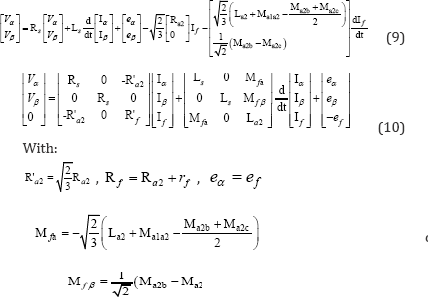
Finally, the machine equations with inter-turn fault (7) in αβ reference frame are written as follows:
As the zero sequence component of the current is zero, the electromagnetic torque expression (2) is:

State space form of fault model
For digital simulation of the electrical machine with
inter turn fault, it is more convenient to express the dynamic
equations in the state space form. The (10) can be written as:

The state vector (x) and input vector (u) are supposed as:

Thus, the machine fault model (10) in the state space form can be expressed as:
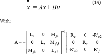
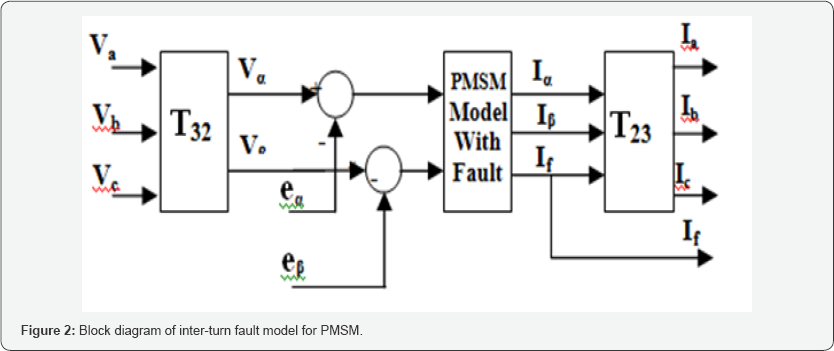
The state space equation (14) can be used for digital
simulation. The simulation block diagram for PMSM with interturn fault
is shown in Figure 2.
Simulation Results for PMSM with Inter-Turn Faults
The proposed fault dynamic model (10) to (11) or (14)
is used to modeling and study the PMSM with stator winding inter-turn
fault. For this purpose, a four pair-pole PMSM. Using MATLAB- Simulink
software, the fault model for PMSM is simulated under various inter-turn
fault conditions.
Winding as in the external circuit is divided to two subwinding as1 and a s2 in series. With such a procedure, the current of the shorted part and flux linked with this branch is accessible.
First, it is considered that fault is occurred 2% of
winding turns in the phase as and the other phases are healthy. The
dynamic fault model is simulated for different values of fault
insulation resistances rf = 10Ω, 1Ω and 0.1Ω. The simulation results, concerning the phase currents ( Iabc ) and the fault current ( if ) and the torque electromagnetic are presented in Figure 3.
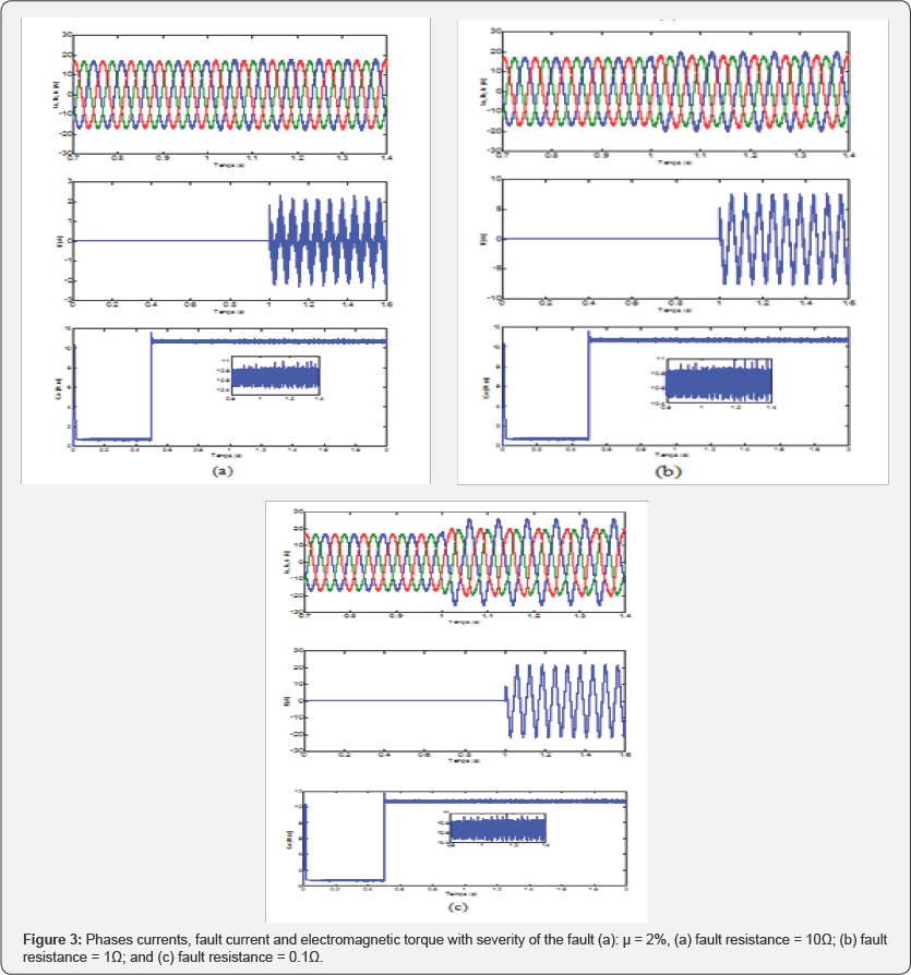
It can be seen that when the resistance to faults
decreases and follows to a complete short circuit, the amplitude of the
fault current increase and the phase currents become more and more
unbalanced, the phase which fault is occurred (as),
will be non-sinusoidal. Furthermore, the phases current will have not
the same amplitude and will be unbalanced. The phase current witch the
turn fault is occurred in (as) is much higher than other phase currents (bs, cs)
where these phases are also affected by the fault. The torque
electromagnetic present increase the fluctuation from the nominal value.
This fault may also produce a small torque ripples.
Secondly, it is considered that fault insulation
resistances 0.1Ω The dynamic fault model is simulated for different
values of the severity of the fault (a): μ = 1%, (b): μ = 2%, (c): μ=
3%. The simulation results, concerning the phase currents ( Iabc ) and the fault current (I) and the torque electromagnetic are presented in Figure 4.
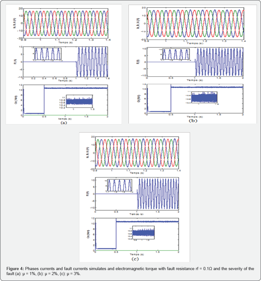
Before the fault the current if is zero. The phase
currents are unbalanced with, in addition to increasing the amplitude of
the current of the defective phase compared to the other phases when
the number of turns in short-circuit increases, the system of phase
currents is unbalanced, although these currents retain the periodic
properties.
In stationary state (as it is the aim of this work),
FFT analysis method is used to characterize signatures of different kind
and strong of the short-circuit faults.
Measurements of stator currents in healthy mode and
faulty mode obtained by applying with different values of the severity
the fault μ, and different values of fault insulation resistances rf .
The Figure 5 & 6
shows the stator current FFT analysis in phase 'a' in healthy mode and
faulty mode obtained by applying a 02% of the severity of the fault and
insulation resistances 0.1Ω.
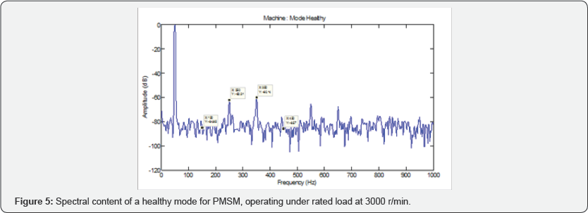
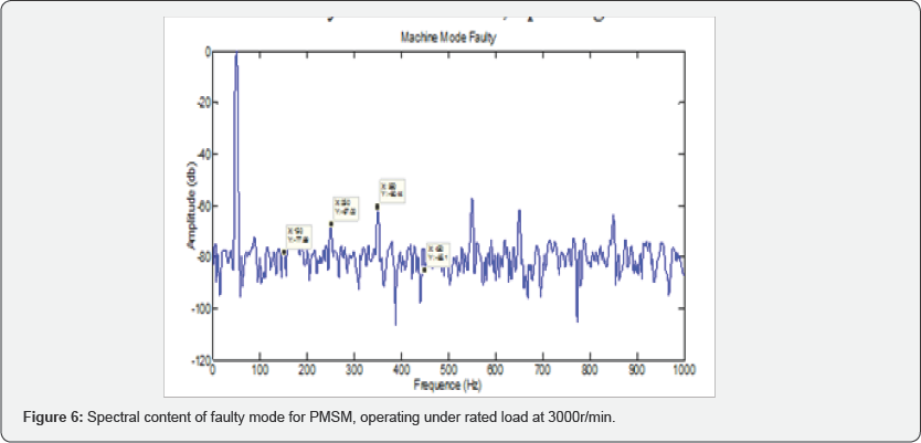

Table 1
shows the stator currents FFT analysis in the case of a single phase
inter-turn fault in phase 'a' with different values of the severity of
the fault (a): μ = 1%, (b): μ = 2%, (c): μ= 3% turns short circuited and
insulation resistances 0.1H at a speed of 3000rpm. It is clear that
third harmonic components are stronger than the healthy operating mode
and there is an increase in this component with growth of the severity
of the fault.
The above study shows in the Table 2,
FFT analysis of stator current in the case of a single phase inter-turn
fault in phase 'a' for 02% of winding turns with different values of
fault insulation resistances rf = 10Ω, 1Ω and 0.1Ω at a
speed of 3000rpm, It can be seen that the phase currents harmonics
components will increase, as the fault resistance decrease rf .

Conclusion
To identify the stator winding fault for PMSM, this
paper proposed a model that can describe both normal and fault
conditions. The model has been verified by comparing the simulation
results with observations in related literature. However, because there
is no quantified comparison, it is difficult to evaluate the accuracy of
the developed model.
The fault detection problem can be approached by
identifying the two parameters associated with fault location and fault
severity. Because of the complex distribution of these two parameters in
the fault model, it is very difficult to design a nonlinear
identification algorithm. The FFT analysis algorithm is proposed to
solve the detection/identification problem indirectly. Simulation
studies on the developed model under both healthy and fault conditions
demonstrate the performance of the proposed algorithm.
The proposed inter-turn fault model seems to be well adapted for PMSM health monitoring and inter-turn fault diagnosis.
Appendix


Comments
Post a Comment