Influence of Wiper and Conventional Inserts at Profile Geometry During Turning of D2 Tool Steel - Juniper Publishers
Juniper Publishers - Open Access Journal of Engineering Technology
Abstract
Latest inventions in the field of manufacturing drive
the new technologies and different sources of production and to design
the various sources to enhance the productivity as well as to reduce the
cost, while maintaining the required specifications and high standards
of the products. For achieving the production with high quality, tool
manufacturers are continuously improving cutting edge, coating, geometry
and the material of the tool. The tool geometry affects different
aspects of tool like cutting temperature, tool wear and tool life,
surface roughness, dimensional accuracy and surface integrity in the
machining. The existing study is an attempt to explore the effect of
wiper and conventional insets at profile turning. In this research
inserts (wiper and conventional) having three different tool of nose
radius (0.4, 0.8 and 1.2mm respectively) were evaluated at cutting speed
(150m/min), feed rate levels (0.05. 0.10, 0.15, 0.20mm/rev), and depth
of cut (0.2mm). Workpiece surface roughness (Ra) dimensional accuracy
and microhardness of the machined surface were assessed. It was found
that in profile turning in case of conventional inserts with larger nose
radius of 1.2mm performed better than the other two inserts in term of
surface roughness and dimensional accuracy. While in case of wiper
inserts surface roughness and dimensional accuracy results were not
better as comparing to conventional inserts. Microhardness under the
machined surface was increased in both the cases of wiper and
conventional.
Keywords: Profile turning; D2 tool steel; Inserts (Wiper and Conventional); Dimensional Accuracy; Surface roughness; MicrohardnessIntroduction
Hard part turning which is also known as hard
turning (HT) is the machining of material having hardness more than 60
HRC, these types of materials are cut with CBN and Ceramics tools [1].
In the hard turning process, not only operating parameters and geometry
of tool are important but also the material composition and tool type
are the elements that influence the surface finish of the product.
Previous literature indicates that, in order to increase efficiency in
terms of tool life, surface roughness, tool geometry and surface
integrity are the parameters that are to be considered [2]. The wiper
technology for turning is made up of series of radii that form the
cutting edge. In wiper insert adjacent to nose radius, 3 to 9 smaller
radii were introduced [3]. To ensure a better surface finish, operating
parameters are important and selected very carefully [4], tool geometry
and material [5], and
surface reliability is very essential for the machined components having
elevated thermal and mechanical stresses [6]. Authors conducted an
experimental study while machining D2 tool steel with wiper inserts and
found that feed rate is the major factor that affects the surface
roughness. Further in depth analysis of surface integrity microhardness
was extended up to 150μm beneath the machined surface, and no white
layer formation was found after machining [7]. Denni Kurniawan et al.
used wiper inserts for the metal removal process of martensitic
stainless steel at different material removal speeds and feed rate, and
found that combination of truncated feed rate and speed generated the
higher tool life with better surface finish [8]. D.M. D’Addona &
Sunil J. Raykar carried an experimental research to find out the effect
of wiper and conventional inserts during turning of oil hardening non
shrinkage steel. From the analysis, it can be seen that wiper inserts
performance in term of surface
finish was better than conventional insert in the simple turning
process. It was also concluded that feed was the most dominant
factor than the other operating parameters that affects the
surface finish [9]. In another study, PCBN tools were employed
to machine AISI D2 steel and noticed that the most reasonable
speeds and feeds were in the assortment of 70-120m/min,
0.08-0.20mm/rev respectively. Higher tool lifespan and metal
removal rate obtained at lower speed and uppermost feed rate
shows that lower speed is more feasible for the machining at
the certain range of parameters combinations; however, highest
feed decreases the tool life [10]. An experimental research was
carried out on the mach inability characteristics of specific
cutting force, power, machining force, tool wear and surface
roughness (Ra) while machining of AISI D2 tool with inserts
(conventional and wiper ceramic). The analysis indicated that
the tool wear decreased by increasing depth of cut up to 0.4mm,
when GC6050WH and CC650 inserts were used it suddenly
increased. It was also noticed that tool wear increased gradually
with the depth of cut while using CC650WG. CC650WG type wiper
insert performance was enhanced in term of exterior roughness
and tool wear [11]. HA Kishawy and MA Elbestawi inspected the
surface integrity and tool wear while machining D2 tool steel.
Effect of different cutting factors on edge preparation, surface
and subsurface damage and tool wear was examined. From the
scanning electron microscope (SEM) analysis it was noticed that
surface integrity conditions changed significantly with various
operating conditions. In addition to that a fine surface finish was
obtained at high cutting speed from worm tool and white layers
were observed on the subsurface [12]. In another experimental
study, during the finishing operation of turning of D2 tool steel
using ceramic wiper (multi-radii) tools, the tool lifespan, flank
wear and exterior roughness were inspected. From the analysis
it was concluded that exterior roughness was in the series of
0.18-0.20μm using wiper tools and tool life was obtained 15min
at high cutting speed [13]. Kopac et al. suggested that surface
finish obtained by wiper inserts is similar in comparison to
machining with conventional tools at low feed rate. Whereas at
high feed rate, conventional tools provide higher value of surface
roughness as compared to wiper inserts [14].
Researchers carried out numerous experiments to examine
the effect of operating limitations on Ra in turning operation [15]
as it is a major parameter used in the performance of machined
components. Rzewski & Wan at, used inserts (conventional and
wiper) in rigid turning process at constant parameters, which are
depth of cut, nose radius, cutting speed, and variable feed rates.
It was concluded that both types of inserts provide similar values
of Ra at lower feed rates [16]. Cakir et al. discovered that, feed
rate had substantial influence on Ra followed by cutting speed.
A greater value of feed rate generates higher exterior roughness,
however cutting speed had an opposing result and depth of cut
had no major influence [17]. Prasad et al. investigated that Ra
values rise with escalation in speed, varying nonlinearly with
augmentation variation of feed conversely; depth of cut was not
affecting much on roughness values. Most of the researchers
concluded in their research that feed rate considerably affect the
surface roughness along with depth of cut and cutting speed [18].
Neslusan et al. found the effect of feed rate (0.10-0.65mm/rev)
while turning bearing steel 100Cr6 at unchanged cutting speed
(150m/min) and depth of cut (0.15mm) and made a comparison
with conventional inserts. Approximately 60% higher surface
compressive residual stresses and ~33% reduced white layer
thickness has been reported. The surface integrity attributes
were recorded when feed rate was low (0.225mm/rev) [19].
Amini & Paktinat [20] used mixed alumina multi radii inserts
while turning Monel K500 at feed rates ranging from 0.12mm/
rev to 0.24mm/rev. Though they report 57% and 60% reduction
in cutting force and Ra respectively as compare to conventional
insert, however, no data related to tool wear has been reported.
Recently, Ferreira et al. [21] evaluated hard turning of AISI H13
steel using multi radii and conventional inserts at four levels of
feed rate (0.05, 0.10, 0.25 and 0.40mm/rev) and at a perpetual
depth of cut (0.20mm). Roughness values (Ra) obtained for multi
radii inserts were approximately 5 times less in comparison to
their conventional counterparts.
Experimental Detail
The current study was conducted to explore the effect
of inserts (wiper and conventional) geometry on the profile
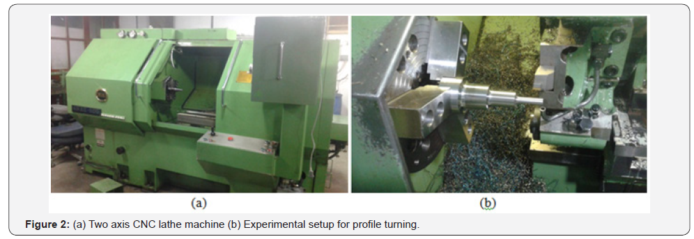
turning of D2 tool steel. Two-axes CNC lathe machine was used
for experiments. Experiments were performed at high chromium
heat treated AISI D2 tool steel with chemical configuration of
C=1.51%, Si= 0.42%, Mn= 0.37%, Cr=15%, Mo=1.3%, V=0.80%.
A bar of dimensions 70 mm diameter and 22mm length with
a hardness value of 59±1HRC was used for experimentation.
Mixed alumina TiN coated ceramic inserts having 71%Al2O3,
28%TiC&1% other were used having conventional and wiper
geometry. Rhombic shaped Wiper tool geometry having 0.4mm,
0.8mm and 1.2mm nose radius corresponding to ISO code CNGA
120404 S01525 WH (0.4mm), CNGA 120408 S01525WH (0.8mm)
and CNGA 120412 S01525WH (1.2mm) [Ref. CC6050WG]. The
conventional inserts had chamfered plus honed edge and also
TiN coating having nose radius of 0.4mm, 0.8mm and 1.2mm
with ISO code CNGA 120404 S01525 (0.4mm), CNGA 120408
S01525 (0.8mm) and CNGA 120412 S01525 (1.2mm) [Ref.
CC6050] (Figure 1).
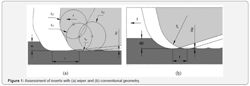
The inserts had an 80° rhombic shape with cutting edge
length of 12mm. The insert thickness was 4.76mm. A single
insert had four cutting edges. The geometry of the inserts
provided 6° clearance angle with a negative rake of 6°, cutting
edge inclination angle of -6° and cutting edge angle of 95°.
Tool holder with ISO code of MCLNR 2020K12 was used
to mount these inserts throughout the experiments. The tool
holder gave rake angles of 5° to tool’s end and back. Similarly,
end cutting edge angle was also 5° while -5° was side cutting
edge angle. The end and back rake angles were -5° as negative
rakes are common in hard machining but the effective rake was
positive.
In the current study two factors involving feed rate at 4
levels and nose radius at 3 levels were investigated using full
factorial design. Each tool nose radius was evaluated against
different values of feed rate (0.05, 0.10, 0.15 and 0.20mm/rev)
at continuous cutting speed (150m/min) and depth of cut (0.2
mm), in order to find out the exterior roughness and dimensional
precision using complete factorial design. All inserts of (0.4,
0.8, 1.2mm) were evaluated at different feed rate value. The
experiments were performed separately for both the wiper and
conventional inserts. Experiments were performed without
using any coolant (Figure 2).
Results and Discussion
Surface roughness
Exterior roughness is the key factor that is used to measure
the performance of the machined part, less value of surface
roughness is necessary to manufacturing work piece, it reduces
the coefficient of friction and wear rate besides improves the
corrosion resistance properties [22].
In the current study, workpiece surface roughness values
were taken at corresponding feed rate with the three types of
inserts while machining at the given conditions of constant
cutting speed, depth of cut and varying feed rate. The values
were also taken at the start and end of tests so as to learn the
range of surface roughness variation for a particular test. An
evaluation length of 4mm was selected to measure Ra value
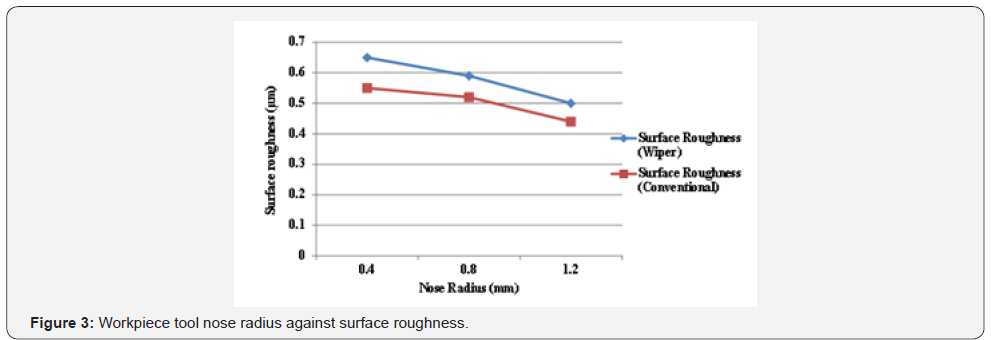
at the profile. From the analysis it was observed that surface
roughness (Ra) values decreased while increasing the nose
radius of the tool, but instead specific cutting energy to some
extent increased with increasing the nose radius because of large
contact area of the tool. The minimum value of surface roughness
0.44μm was achieved with the conventional tool at large nose
radius of 1.2mm. So conventional tools provided better results
in comparison to the wiper tools in the profile turning. Following
Figure 3 represent the workpiece surface roughness with respect
to each tool nose radius.
Similarly, each nose radius was evaluated to investigate the
feed rate against surface roughness. From the graphs it was
perceived that, surface roughness increased while increasing the
feed rate due to large uncut chip thickness. While in comparing
both the tools, conventional tools provided better results in term
of surface roughness than wiper tools in each tool nose radius.
Following graphs represent the workpiece surface roughness with respect to feed rate for each tool nose radius. A similar kind
of trend was observed in the foremost influence plot for surface
roughness. The graph also indicated that workpiece surface
roughness increased with the rise in feed rate. Maximum surface
roughness was observed at maximum feed rate, while lower
value of surface roughness was noticed at smaller value of feed
rate for both the wiper and conventional tools. The main effect
plot in Figure 4, 5 showed that, in the process of profile turning,
better results were achieved by conventional tools as compared
to the wiper tools.


Dimensional accuracy
The dimensional accuracy is the important key to ensure the
achievement of correct functioning of parts machining. Nowadays
many manufacturers try to produce good machining parts or
components with good dimensional tolerance in order to fulfil
customer requirements. Normally, dimensional accuracy of the
machining parts depends on the machining process that involves
in the selection of cutting parameters. In the current research
dimensional accuracy of the machined surface against feed rate
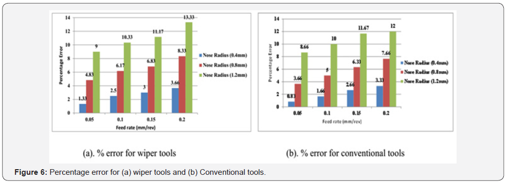
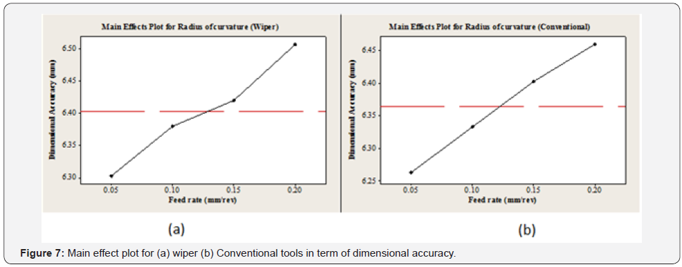
for each tool nose radius was investigated. The analysis reveals that, with the dimensional accuracy increased by increasing
the feed rate for both the cases. It was also observed from the
graphs that percentage error for the conventional tools was less
than the wiper tools. The conventional inserts provided better
dimensional tolerance in comparison to the wiper inserts in the
profile turning process, the main effect plot in Figure 6 showed
that surface finish decreased by increasing feed. In the process
of profile turning, better results were achieved by conventional
tools as compared to the wiper tools. The main effect plot in
the Figure 7 indicated that higher value of radius of curvature
was achieved by wiper tools in comparison to the conventional
tools, So a significant deviation was notice in term of radius of
curvature in the wiper tools.
Micro hardness
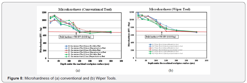
Microhardness under the machined surface was measured
at a distance of (10, 30, 60, 100,120, 150,200 and 300μm).
Indenter was placed at the workpiece surface at different
location in the zigzag form to measure the diagonals of the
indenter. Microhardness was measured for the samples that
were machined for both the new and worn tools. Following
observations were noticed from the graphs. It was observed
from the graph that microhardness was increased under the
machined surface, and uniformly decreases as the depth under
the machined surface increased. It was also observed from the
graph that microhardness under the machined surface for both
new and worn tools at the distance of 10μm was increased
1.4 to 1.6 times more than the bulk hardness of the material.
In comparison to the new and worn tools similar results were
obtained that microhardness was increased near the machined
surface. Although larger values of microhardness were observed
under the machined surface at 10μm for worn tools because
of mechanical stresses and vibration tendencies increased. It
was also noticed that micro hardness become stable under the
machine surface after 150μm (Figure 8).
Acknowledgment
The authors appreciatively acknowledge the management
and laboratory staff of Pakistan Industrial and Technical
Assessment Center (PITAC) Lahore, for their cooperation and
permission for using machines and other measuring equipment.
Authors also thanks to the lab staff of Department of Material
and Metallurgical Engineering University of Engineering and
Technology Lahore, Pakistan.
Conclusion
The statistical analysis revealed that tool geometry and
cutting parameters have noteworthy influence on the work piece
surface finish. It was found that, in profile turning process while
using conventional inserts with larger nose radius of 1.2mm
produced better surface finish than the other two nose radii i.e
0.8mm and 0.4mm. The surface roughness at 1.2mm nose radius
is 15% less than that at 0.8mm and 20% less than that at 0.4mm
nose radius. Almost same trend appeared while using wiper
inserts of respective nose radii. As comparison between wiper
and conventional inserts, at 1.2mm nose radius, conventional
inserts resulted 20% lower surface roughness than as with
wiper inserts and it remained lower at other nose radii also. It
was also established that increase in the feed rate value resulted
the decrease in surface finish but surface finish for conventional
inserts was 5% better than that with wiper inserts. While in
case of dimensional accuracy, conventional inserts with larger
nose radius performed better than wiper tools. At lowest nose
radius, dimensional accuracy in term of profile turning from
wiper inserts was almost 32% less than that with conventional
inserts and at higher nose radius this difference of dimensional
accuracy reduced to 4% between wiper and conventional inserts.
Microhardness shows a mix behavior for wiper and conventional
inserts and same trend is appeared for both inserts.
For more articles in Open Access Journal of
Engineering Technology please click on:


Comments
Post a Comment