Juniper Publishers High Gain Observer for Sensorless Input-Output Linearizing Control for Induction Motor with Broken Rotor Bar Fault.
Juniper Publishers Engineering Technology Open Access Journals

High Gain Observer for Sensorless Input-Output Linearizing Control for Induction Motor with Broken Rotor Bar Fault.
Authored by A Menacer
Abstract
The aim of this paper is the broken rotor bar
diagnosis for the sensorless nonlinear control (NLC) of the induction
motor (IM). The strategy of control is based on the input output
linearization control, using nonlinear high gain observer (HGO), in
order to preserve the speed regulation and compensate the fault effect
and to ensure the service continuity of the machine. The effect of the
broken rotor bar is evaluated through the analysis of the direct current
components Ids. This information can be used as an indication for the
fault diagnosis.
Keywords: Induction motor; Diagnosis; Broken rotor bars fault; Nonlinear control; Input output linearization control; High gain observerAbbreviations: IM: Induction Motor; FOC: Field Oriented Control; HGO: High Gain Observer
Introduction
The induction motor (IM) is known for its robustness,
simplicity of operation and low costs and maintenance free. Like any
motor exposed to mechanical or electrodynamics forces, it is lead to
failures [1],
it’s also may be caused by manufacturing fault, designing fault of the
engineer, environment and poor technical knowledge of the job about in
handling the motor [2].
On the other hand, vector control provides a good
performance during transient and permanent phases. However, it requires
knowledge of mechanical speed and rotor flux [3].
The difficulties of using field oriented control (FOC) arise from the
modelling uncertainties due to parameter variation, magnetic saturation,
load disturbances. To ensure a good dynamic performance, various robust
control strategies for induction motor drives have been cited in the
literature [4,5].
However, the input-output linearization control has focused attention
owing to simple design, the perfect decoupling between the rotor speed
and the flux, fast dynamic response, easy implementation and robustness
to parameter variations, and also for load disturbances [6,7].
Fault detection in electrical machines has been the subject of researches for many years [8].
Vibration is used for the detection of mechanical problems, broken
rotor bars and stator short circuits in induction motor. Vibration
analysis techniques are usually installed on costly and sensitive
machines, where the cost of such systems can be justified [9].
That is why some researchers are looking to analyze other quantities in order to solve this problem. In [10,11]
d (direct) current axis components have been looked in closed-loop. The
rotor speed and a rotor flux are estimated by high gain observer (HGO) [12,13].
The controller is based on the theory of feedback linearization. Where,
the reduced model of IM in healthy and faulty states is used.
This paper is organized as follows. In section 2, the
dynamic of the reduced model of IM is described. The input-output
linearization control is designed for the speed and flux magnitude
controls of an IM are showed in section 3. The HGO required for the
rotor flux and rotor speed estimation are presented in section 4.
Section 5, provides numerical simulation results of the proposed control
technique in healthy and faulty states of the IM, followed by the
conclusion.
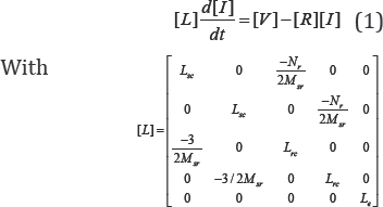
Induction Motors Model with Broken Rotor Fault
The dynamic equations of IM can be expressed as follows [14]:
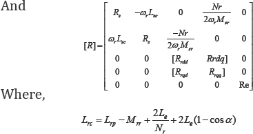
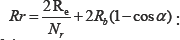 Electrical angle of two rotor adjacent mesh�s.
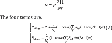
In Eq. 2, the summation is applied to all bars with fault. Rbfk is the increased resistance of the bar index k from its initial value before the fault.
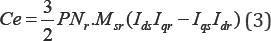
The electromagnetic torque developed by the motor is expressed in terms of rotor currents and stator currents as:
The model considered allows studying the behaviour at the healthy and faulty states of the IM in different operation cases.
Design of a Nonlinear Input-Output Feedback Linearizing Controller for Induction Motor
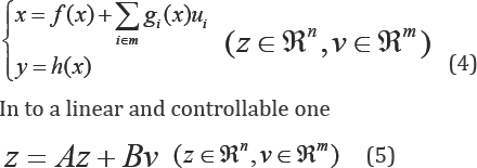
The input-output control problem is to find a state
feedback such that the transformed system is input-output decoupled that
is, one input influence one output only [15]. The technique requires measurements of the state vector x in order to transform a multi-input nonlinear control system:

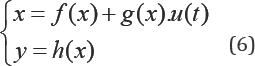
The control system is depicted in (Figure 1) [16]. The state space model of induction motor in the (a,P) frame coordinate is giVen by:
Where the state and commands vectors:

The decoupling matrix D(x) is singular if and only if Φ2r
zero which only occurs at the start up of the motor. That is, to fulfil
this condition one can use in a practical setting, an open loop
controller at the start up of the motor, and then switch to the
nonlinear controller as soon as the flux goes up to zero. If the
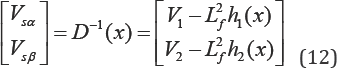
decoupling matrix is not singular, the nonlinear state feedback control
is given by:
This controller linearizes and decouples the system, resulting in:
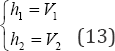
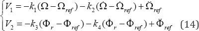
The closed loop system (13) is input-output decoupled and linear. To ensure perfect tracking of speed and flux references, V1 and V2 are chosen as follows:
Nonlinear High Gain Observer Design for Induction Motor
The dynamic behaviour in general of the induction
motor belongs to a class of relatively fast systems. For computational
issue, the high gain observer which admits an explicit correction gain
can be considered as one of the most viable candidate in the problem of
state estimation [12,17]. To study the observation and control of the induction motor, we adopt this method in our model (6), given by:
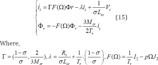
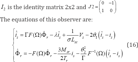
Where  and
and  are respectively the estimates of Is and Φr , Which β1, is a positive real. Therefore, the adaptive Scheme for speed estimation is given by:
and are respectively the estimates of Is and Φr , Which β1, is a positive real. Therefore, the adaptive Scheme for speed estimation is given by:
Where,  , k and kt are respectively the proportional and integral constants.
, k and kt are respectively the proportional and integral constants.Simulation Results
The sensorless input-output linearization control of
induction motor used in healthy and faulty states: 1.1kW, 220V, 50Hz,
2-pole, a rotor with 16 bars were carried out using the Matlab/Simulink
simulation package. The system parameters of the induction motor tested
in this study are given in Appendix.
Healthy machine
To illustrate the performances of controller in
healthy state of the machine, a simulation with reference speed equal to
1000rpm is realized in Figure 2, a nominal load torque equal to 3.5 Nm is applied at t=0.5s.

The electromagnetic torque follows the load torque and stator phase current have a very good dynamic. Quadratic rotor flux Φqr is maintained to almost zero, direct rotor flux Φdr tracks the reference values adequately well.
The speed reverse test is realized by changing the
speed reference from 30 rpm to -30 rpm at t=1s with a nominal load
torque 3.5 Nm is applied at t=0.5s in Figure 3.

The good performance such as robustness and
convergence of the sensorless input-output linearization control when
the induction motor operates in low reference speed. It shows that
estimate rotor speed observer and the real rotor speed converge to the
reference speed with very less errors.
Machine with adjacent two broken rotor bars fault
In this case the sensorless input-output
linearization control of the induction motor with fault is considered.
Two adjacent broken rotor bars fault are applied at t=1s and the machine
operate at 1000 rpm with a nominal load torque 3.5Nm applied at t=0.5s.
The simulation results of sensorless input-output
linearization control using high gain observer of the induction motor
with adjacent two broken rotor bars fault are shown in Figure 4.
The rotor speed and torque give no information about the fault effect,
due to the closed loop of input-output linearization control which mask
and compensate the effect of the fault. However, the direct current Ids
is affected by the fault through the fluctuations. This information can
be exploited for the online diagnosis of the machine in closed loop.

Conclusion
In this paper, a sensorless input-output Linearizing
control for the induction motor is considered with broken rotor bars
fault. The controller shows a good performance of the induction machine
control in healthy and faulty states.
Therefore reveals a powerful sensorless input-output
Linearizing control using high gain observer for estimate the rotor
speed and Flux, Where The effect of loop control by using the speed
regulator ensures the rejection of ripples, therefore the correlation
with the fault severity is lost. The fault effect didn't affect the
rotor speed; unlike the direct current components Ids which offer a good indication for the fault effect in closed loop.
Appendix
For the simulated induction motor
pn : Output power 1.1kW
Vs : Stator voltage 220V
fs : Stator frequency 50Hz
p: Pole number 1
Rs : Stator resistance 7.58W
Rr : Rotor resistance 6.3W
Rb : Rotor bar resistance 0.15mW
Re : Resistance of end ring segment 0.15mW
Lb : Rotor bar inductance 0.1μH
Le : Inductance of end ring 0.1μH
Lsf : Leakage inductance of stator 26.5mH
Msr : Mutual inductance 46.42mH
Ns : Number of turns per stator phase 160
Nr : Number of rotor bars 16
L: Length of the rotor 65mm
g0 : Air-gap mean diameter 2.mm
J: Inertia moment 0.0054kgm2
F: Coefficient of damping 0.0029Nm/rad/s
Ce , Cr : electromagnetic torque, load torque
For more articles in Open Access Journal of Engineering Technology please click on:
https://juniperpublishers.com/etoaj/index.php
To read more…Fulltext please click on:
https://juniperpublishers.com/etoaj/ETOAJ.MS.ID.555554.php
For more articles in Open Access Journal of Engineering Technology please click on:
https://juniperpublishers.com/etoaj/index.php
To read more…Fulltext please click on:
https://juniperpublishers.com/etoaj/ETOAJ.MS.ID.555554.php


Comments
Post a Comment